Digital Timer - Introduction
GliderScore DigitalTimer is a companion to Gliderscore.
The program
- Makes all audio announcements, including timer announcements
- Runs a very accurate timer and displays the time on screen
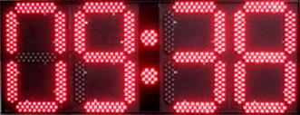
- Optionally outputs the time to a digital clock display panel (AerobTec LED panel shown)
- No need for pre-recorded 'timing' .mp3 files
Running the Digital Timer
- Create the Playlist using Gliderscore.
See 'Create Playlist' tab for details.
- Open the DigitalTimer program (from within Gliderscore).
- If using a display panel and it does not work with the Digital Timer program, contact me to resolve the issue.
When using the DigitalTimer
- Set your computer to stay awake. If it goes to 'sleep', so will the DigitalTimer.
- Disable any anti-virus program from running.
McAfee Anti-Virus has been shown to intermittently interrupt the DigitalTimer.
Other anti-virus programs may well do the same. Avast seems to be OK.
Watch this video to see the program being used at a competition in Holland, or
this earlier video made in a workshop including the use of a one minute landing window.
Videos courtesy of Arjan Harmans.
The DigitalTimer program can be used with or without a display panel.
Don't have a display panel? Click on the 'Display Panels' and 'Display Panel Build' tabs.
The first step is to create the Playlist.
Click on the 'Create Playlist' tab to learn more.
GeneralFile MaintenancePlaylist SettingsCreate Playlist/Open TimerMerge Playlists
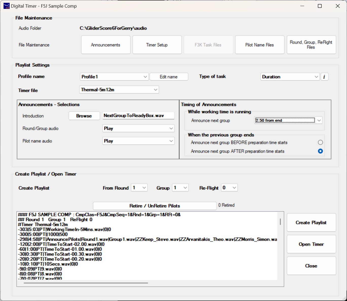
Digital Timer - Create Playlist - General
Clicking on 'Digital Timer' from the competition setup screen will bring up this screen.
There are four sections.
- File Maintenance - gives you complete control over your Timers and related files
- Playlist Settings - allows you to customise your playlist
- Create Playlist/Open Timer - creates the Playlist that the Timer will use, and opens the Timer
- Merge Playlists - about merging playlists from two (or more) separate competitions.
Take the time to look through the information about
File Maintenance and Playlist Settings now.
GeneralTimersAnnouncementsF3K TasksF5K TasksPilot NamesRounds/GroupsRecord Audio
Digital Timer - Create Playlist - File Maintenance - General
There are a number of files needed for the Digital Timer.
- Announcements - audio recordings of announcements to be made while the timer is running
- Timers - you control how each timer will run including when announcements and sounds (beeps) should play
- F3K Task Files - recordings describing each F3K task (can be included in the playlist)
- Pilot Name Files - recordings of each pilot name for pilot name announcements
- Round, Group, ReFlight Files - recordings of round, group and reflight numbers
A special set of Announcement files has been put together to work with GliderScore.
These are all included with the full download and with upgrades to version 6.45.
There is little need to re-visit any of these files once your timers are set up.
A preliminary set of Timers is included with the full download and with upgrades to version 6.45.
See the following tabs for more details.
Digital Timer - Create Playlist - File Maintenance - Timers
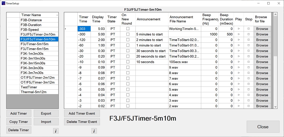
This is where you decide everything about your timers.
Timers can be added, deleted or copied.
Export or Import timers (file extension '.timer').
If creating a new timer, it is highly recommended that you start by copying an existing timer.
As the 'Timer Time' increases, the clock counts down from the 'Displayed Time'.
The 'Displayed Time' is always positive.
The difference in seconds between any two consecutive 'Timer Times' will typically be exactly
the same as the difference in seconds between the two 'Displayed Times'.
For each timer event, set the following
- Timer Time - the time, in seconds, at which an announcement or a beep should happen.
Negative values generally indicate preparation time. Positive values indicate working time and/or landing time.
- Displayed Time - the time to be displayed (at the Timer Time) on the screen and/or an external display.
Examples: Enter 100 for 1:00, enter 500 for 5:00, enter 5 for 00:05.
- Timer State - indicates the timer's progress through these states -
PT=preparation time; TT=testing time; NF=no-flying allowed; WT=working time;LT=landing time.
- On New Round - if ticked, the timer event will only happen when there is a change in round number.
This does not apply to the first round in the playlist. Use this to extend the preparation time
between rounds.
- Announcement - a note of what the announcement, if any is to be. May be left blank.
- Announcement File Name - a file from 'Digital Timer Announcements' that is to be played at this time.
You can type in the file name or browse to it using the 'Browse' button.
- Beep Frequency - If a sound is to be played, this is the frequency in hertz.
- Beep Duration - If a sound is to be played, this is the duration in milliseconds (1000ms = 1s).
You cannot have beeps and announcements at the same time.
You can introduce silence by adding a Timer event before any announcement.
For example, putting a Timer event at -310 with a 'Displayed' Time of 5:10 (or even 0:00) will give 10 seconds silence before a '5 minutes' warning.
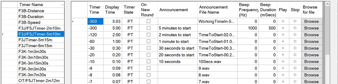
Negative Timer Times indicate Preparation time, Testing time or No-Fly time.
The computer clock digits will be orange.
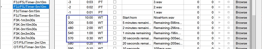
Positive Timer Times indicate Working Time and/or Landing Time.
The computer clock digits will be green.
If, during working time, the Displayed time increases (in this case from 00:01 to 00:30), this becomes landing time. The computer clock digits will be blue.
Digital Timer - Create Playlist - File Maintenance
Announcements
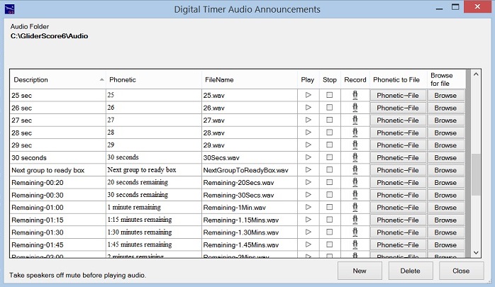
These are recordings of all possible announcements during the running of the timer.
For example, "5 minutes to start", "4 minutes to start", ... "2 minutes remaining", 1 minute remaining".
When creating or maintaining a timer, you choose what audio file (or beep) to play and at what time.
You can replace the recordings provided with your own recordings. The file types allowed are .wav and .mp3.
Recordings can be made
- externally to GliderScore, copied into the Audio folder and then chosen using the Browse button
- within GliderScore by clicking on the microphone icon and using a microphone
- generated by GliderScore by clicking on the 'Phonetic to File' button (uses the text in the 'Phonetic column'
Many of the announcement files supplied with GliderScore have come from the F3JTimer package.
Digital Timer - Create Playlist - File Maintenance
F3K Task Announcements
F3K Task announcement files can be generated by the program or recorded by the user.
GliderScore automatically generates them for you when you first activate the Digital Timer or Audio Player.
Suitable files are also available for download from the
F3KScore
website and perhaps other websites.
Options for creating/enabling sound files.
- Generate from the text entered in the 'Phonetic' column. Click on the 'Phonetic→File' button.
The speed at which the text is spoken, and the volume can be adjusted in Synthesizer Settings.
- Use a file created externally. Copy the file to the 'Audio' folder and then browse to it to create the relationship.
- Record your own voice file. Click on the 'Record' icon and follow the directions.
See the 'Record Audio' tab for more details.
Digital Timer - Create Playlist - File Maintenance
F5K Task Announcements
F5K Task announcement files can be generated by the program or recorded by the user.
GliderScore automatically generates them for you when you first activate the Digital Timer or Audio Player.
Options for creating/enabling sound files.
- Generate from the text entered in the 'Phonetic' column. Click on the 'Phonetic→File' button.
The speed at which the text is spoken, and the volume can be adjusted in Synthesizer Settings.
- Use a file created externally. Copy the file to the 'Audio' folder and then browse to it to create the relationship.
- Record your own voice file. Click on the 'Record' icon and follow the directions.
See the 'Record Audio' tab for more details.
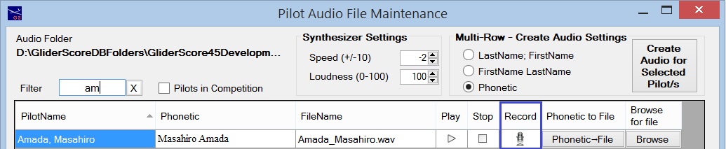
Digital Timer - Create Playlist - File Maintenance
Pilot Name Announcements
Pilot name announcement files can be generated by the program or recorded by the user.
GliderScore automatically generates pilot name audio for you when you first activate the Digital Timer or Audio Player.
Using the selections available for pilot name (Multi-Row - Create Audio Settings)
it is possible to select one or a number of pilots and generate files based on your selection.
Click on the 'Create Audio for Selected Pilot/s' button.
Options for 'speaking' the pilot name.
- LastName; FirstName
- FirstName LastName
- Phonetic
Options for creating/enabling sound files.
- Generate from the text entered in the 'Phonetic' column. Click on the 'Phonetic→File' button.
The speed at which the text is spoken, and the volume can be adjusted in Synthesizer Settings.
- Select one of the Name format options in the 'Multi-Row - Create Audio Settings' list.
Select a pilot or pilots.
Click 'Create Audio for Selected Pilot/s'. New audio is created for all selected pilots.
- Use a file created externally. Copy the file to the 'Audio' folder and then browse to it to create the relationship.
- Record your own voice file. Click on the 'Record' icon and follow the directions.
See the 'Record Audio' tab for more details.
Digital Timer - Create Playlist - File Maintenance
Round, Group and ReFlight Announcements
GliderScore automatically generates these for you when you first activate the Digital Timer or Audio Player.
These are the announcement files for Round, Group and ReFlight numbers.
ReFlight announcements are left out of the playlist if the ReFlight number is 0 (zero).
Options for creating/enabling sound files.
- Generate from the text entered in the 'Phonetic' column. Click on the 'Phonetic→File' button.
The speed at which the text is spoken, and the volume can be adjusted in Synthesizer Settings.
- Use a file created externally. Copy the file to the 'Audio' folder and then browse to it to create the relationship.
- Record your own voice file. Click on the 'Record' icon and follow the directions.
See the 'Record Audio' tab for more details.
Digital Timer - Create Playlist - File Maintenance
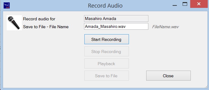
Record Audio
To record audio, click on the icon that you see in the File Maintenance screens.
To successfully record audio, do the following -
- Make sure that your microphone is working.
- and click on the 'Start Recording' button.
- When finished speaking click on the 'Stop Recording' button.
- Click on 'Playback' to listen to your recording.
- Click on 'Save to File' to save the recording to the file named above.
Digital Timer - Create Playlist - Playlist Settings
You can configure and save up to eight playlist Profiles. Be sure to give each Profile a meaningful name.
Each profile must be specific to a particular task.
Tasks available are Duration, Distance, Speed, F3K and F5K.
Select the Profile that is appropriate for your competition.
Playlist Settings
(for F3K and F5K, see Playlist Settings below)
These selections control how your playlist is put together.
- Profile name - give your Profile a meaningful name
- Profile for task - select the type of task for which this Profile will be used
- Timer file - select the Timer file to use
- Pilot name audio - select pilot name audio option (None; Play; Play twice)
- Announcements - Timing
You can choose to have announcements for the current round played either
before the timer starts for preparation time or after preparation time has started.
If you choose the latter, the announcements will start 5 seconds into preparation time.
You can choose to make announcements for the NEXT group during working time by making a timing selection.
Choices are 2:50, 3:50, 4:50, 2:50 X 2, 3:50 X 2 , 4:50 X 2 from the end of working time.
The 'X 2' options will play the round, group and name files twice.
If NOT announcing pilots for the next group during working time, select 'None' from the drop down box.
- Announcements - Selections
Introduction - Choose an introduction audio file. It might announce "Next group, please go to the ready box".
Clear all text from the box to cancel any introduction.
Choose to play round and group audio.
Choose to play pilot names.
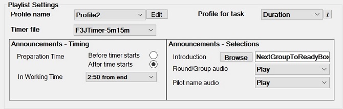
F3K and F5K Playlist Settings
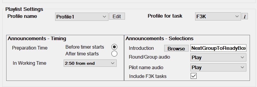
These selections control how your playlist is put together.
F3K and F5K have the same playlist settings.
- Profile name - give your Profile a meaningful name
- Profile for task - select F3K (or F5K) as the task for which this Profile will be used
- Announcements - Timing
You can choose to have announcements for the current round played either
before the timer starts for preparation time or after preparation time has started.
If you choose the latter, the announcements will start 5 seconds into preparation time.
You can choose to make announcements for the NEXT group during working time by making a timing selection.
To make announcements for the next group during working time, make a timing selection.
Choices are 2:50 or 2:50 X 2 from the end of working time.
The '2:50 X 2' option will play the round, group and name files twice.
If NOT announcing pilots for the next group during working time, select 'None' from the drop down box.
- Announcements - Selections
Introduction - Choose an introduction audio file. It might announce "Next group, please go to the ready box".
Clear all text from the box to cancel any introduction.
Choose to play round and group audio.
Choose to play pilot names.
Choose to play F3K (or F5K) task descriptions.
Digital Timer - Create Playlist/Open Timer
SELECT FLIGHT GROUP
Select the flight group (Round; Group; ReFlight) where you want the playlist to start.
RETIRE / UNRETIRE PILOTS
If pilots have retired, or rejoined the competition, click on 'Retire / UnRetire Pilots' button to mark these pilots.
Retired pilots are excluded from the playlist.
Pilots retired (or unretired) here are also marked in the 'Pilot Entry' screen.
CREATE PLAYLIST
Click on 'Create Playlist' to generate the playlist file.
Review the playlist shown at the bottom of the screen.
The playlist file is called '~\Audio\GliderScoreDigitalPlaylist.m3u'.
OPEN TIMER
Click on 'Open Timer' to open the Digital Timer program and then start the playlist playing.
Digital Timer - Merge Playlists
It is possible to merge the playlists from two (or more) competitions to create a single continuous playlist.
The trigger to access this feature is that all competitions involved have the same competition date.
A typical use case is where separate competitions are being run for Seniors and Juniors or F3K and F5K.
The system automatically generates audio files to 'speak' the name of each competition.
These audio files are named Competition1.wav, Competition2.wav, ... and are created in the Audio sub-folder.
If the computer generated files to not correctly 'say' the competition names, replace them with locally produced files.
These competition name files are inserted in the playlist ahead of the round and group announcements.
The merge process works round by round.
In each round the playlist for the first competition is followed by the playlist of the second competition.
The sequence will look something like this:
Round 1
Competition 1 Round 1 Group 1
Competition 1 Round 1 Group 2
Competition 1 Round 1 Group 3
Competition 2 Round 1 Group 1
Competition 2 Round 1 Group 2
Round 2
Competition 1 Round 1 Group 1
Competition 1 Round 1 Group 2
Competition 1 Round 1 Group 3
Competition 2 Round 1 Group 1
Competition 2 Round 1 Group 2
To begin, create a playlist for the first competition to fly.
Open the next competition.
Click to create a playlist in the usual way.
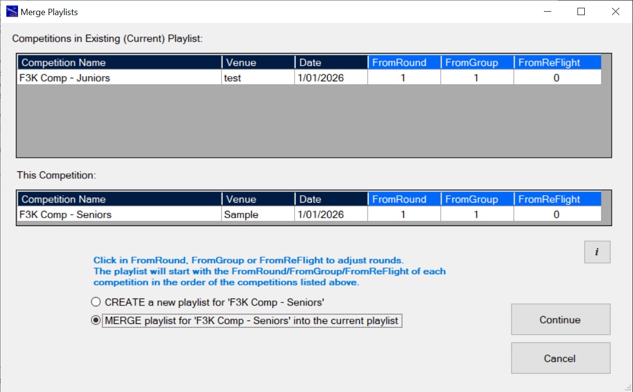
You will see the 'Merge Playlists' screen because the two competitions have the same date.
Choose CREATE to create a playlist for just the current competition or MERGE to merge the playlists together.
In this case choose MERGE.
Click Continue to generate the merged playlist (or Cancel to abandon the operation).
Repeat the process for as many competitions as required.
Click on the 'Open Timer' button within any of the merged playlist competitions to play the merged playlist.
If the competitions run perfectly smoothly then there is no more to do.
Sometimes things do not work out perfectly.
Changes have to be made.
For example, the Seniors competition might end the day without completing the round in progress.
The next day you want to start with the unfinished seniors round and then move back to the juniors.
This is how to do it.
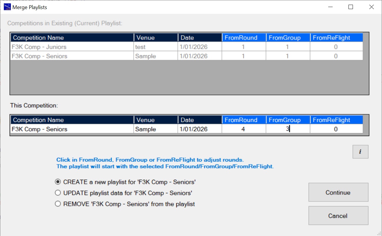
- Open the seniors competition and go to 'Create Playlist'.
- Select the CREATE option (because we now want the seniors to start the next day).
- Edit the FromRound (4) and FromGroup (3) numbers.
- Click on 'Continue'.
- The playlist starting at round 4 group 3 is created.
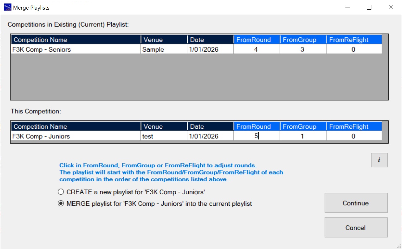
Next, go to the juniors competition.
- Open the juniors competition and go to 'Create Playlist'.
- The juniors had completed round 4 so they will start at round 5.
- Select the MERGE option and edit the FromRound for juniors to 5.
- Click on 'Continue'. The merged playlist is created.
Click on 'Open Timer' to play the merged playlist.
It is important to know that the FromRound, FromGroup and FromReFlight fields can all be edited if they are not greyed out.
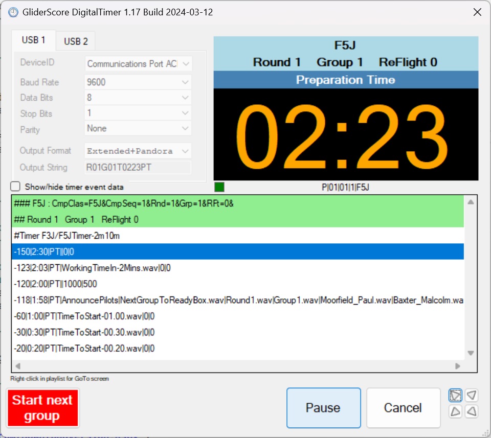
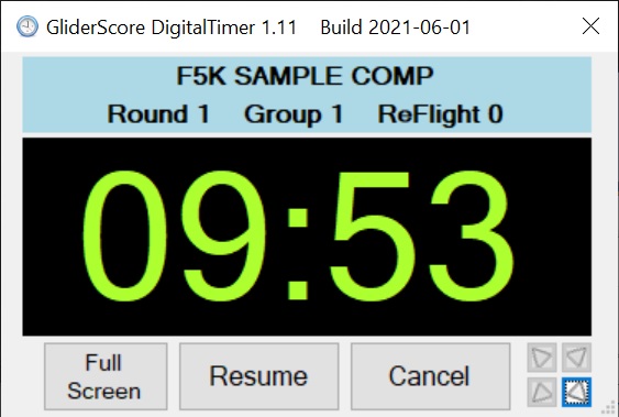
Digital Timer - Open Timer
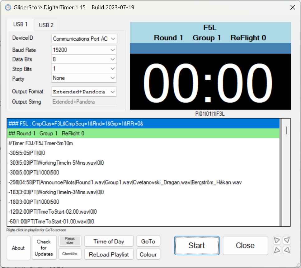
Digital Timer
This screen appears when you click on 'Open Timer' within GliderScore.
When you click on 'Start' audio output goes to the audio port of your computer.
Also, if selected, output will be sent to your computer's COM ports (via USB adapters).
Digital Timer - Start Next Group
After clicking on 'Start' the screen changes and reveals the 'Start Next Group' button (coloured red)
Click the 'Start Next Group' button to immediately start the Timer at the start of the next flight group.
There are no warnings or second chances with this button.
Be careful.

Scheduled Start Time
Scheduled Start
Right-clickingn the Start button opens the Scheduled Start Time screen.
Set the Scheduled Start Time (the time at which the Timer will start).
Optionally, elect to upload files to the cloud that are needed by GliderTimer devices.
Click the Start Countdown button.
This window will close and the Timer will start when the countdown reaches zero.
Serial (COM) Port Settings (for external devices)
From Version 1.10 the Digital Timer can output to two separate COM ports.
These are labelled USB1 and USB2.
This allows separate settings to drive your display panel and your Pandora devices.
For example:
USB1 with 'Extended Protocol' to drive an Embedded-Ability display.
USB2 with 'Extended+Pandora' to drive the Pandora devices.
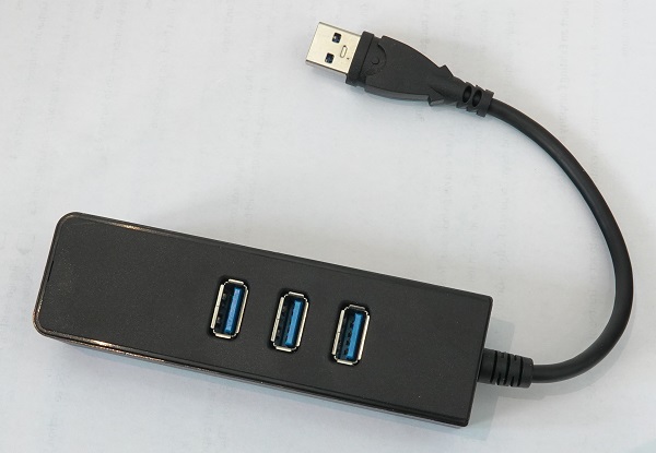
Typically COM ports are made available by means of a USB to Serial port adapter.
If you only have one USB port available you will need to use a USB hub like this one.
DigitalTimer scans for connected devices as soon as the program is started.
Plug in all devices before starting the DigitalTimer.
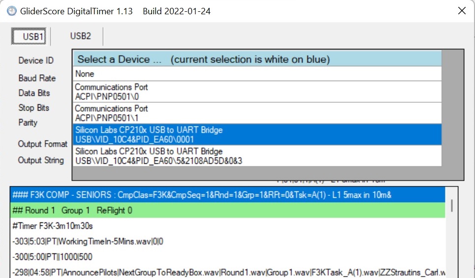
To select your USB devices, hover the mouse over the DeviceID area.
A list will appear like the one shown. Click on your selection.
Click on 'None' to clear your selection. This does not clear the other port settings (Baud rate etc.).
To close the list, move the mouse away from the list.
If using two Silicon Labs devices.
Silicon Labs gives all CP210x chips the same serial number, 0001.
You will notice that 0001 is the last part of the DeviceID.
If you have two devices using the Silicon Labs chips
- the first device plugged in will have 0001 as the serial number.
- the second device will have a different serial number (allocated by Windows).
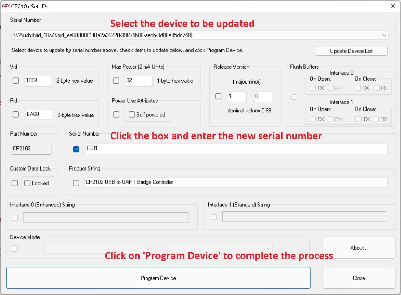
It is recommended to change the serial number on one of the devices to '0002'.
This avoids Windows having to allocate a (temporary) serial number.
You can change the serial number on your devices using a Silicon Labs program called CP210xSetIDs.exe.
Get the program from Silicon Labs website or download it here.
The download file is CP210x_LegacyUtilities.zip and includes a number of utility programs.
Output Format
If using an external display, select the Output Format that is specific to your display.
You can use a different Output Format for Pandora devices if required.
You can use one Port for the display and the other for the Pandora devices.
The currently supported formats are
- mmss \r (the minutes digits, the seconds digits, the Ascii character for Carriage Return)
- Ammss \r (the letter A, the minutes digits, the seconds digits, the Ascii character for Carriage Return)
Both Aerobtec and Embedded-Ability displays work with this setting, but round and group numbers will not display.
- Aerobtec for Aerobtec displays.
This format displays round and group numbers during name announcements.
- Embedded-Ability for Embedded-Ability displays.
This format displays round and group numbers during name announcements.
- Extended Protocol for displays programmed to show round, group and time data.
This format has been created for a pilot who plans to share information about his display before December 2018.
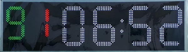 The output format is R99G99T9999+AA+CR
R99 - 99 is replaced by the round number
G99 - 99 is replaced by the group number
T9999 - 9999 is replaced by two characters for minutes and two characters for seconds
AA - two character code for the timer state (PT prep time; WT working time: LT landing time; ST sleep time; DT display time-of-day)
This allows for the possibility of changing the display colour according to the timer state.
CR is the ascii character for Carriage Return.
A typical output string could be R09G01T0652WT+CR
- Extended+Pandora to drive Pandora devices.
 With this output format two separate signals are sent with a 100ms delay between them.
The first signal is exactly the same as the 'Extended Protocol' timing signal as above.
100ms later a signal is sent that gives extra information for F3K/F5K pilots.
The Pandora devices display this information provided that they have the latest updated software.
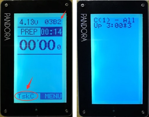
The information sent is the round, group, flight number (for task C, otherwise 0), task code and description.
Flight number is important for task C (both for F3K and F5K) where up to 5 flights may be involved in a round.
The output string is P|RR|GG|F|TaskCodeAndDescription+CR
P is for Pandora; RR is for round number; GG is for group number; F is for flight number (for task C, otherwise 0).
A typical 'Pandora' output string could be P|05|01|1|C(3) - AllUp 3:00*5+CR.
In the image '03' is the round, 'B' is the group (A=1;B=2;C=3,..) and '2' is the flight number.
For more information about Pandora contact Robust at zhouyinghang(at)gmail.com.
- Extended+RGB to drive colour capable displays.
The output format is R99G99T9999+AA+RRR+GGG+BBB+CR
The colour code that is output is the RGB code for the colour selected according to the timer state.
R99 - 99 is replaced by the round number
G99 - 99 is replaced by the group number
T9999 - 9999 is replaced by two characters for minutes and two characters for seconds
AA - two character code for the timer state (PT prep time; WT working time: LT landing time; ST sleep time; DT display time-of-day)
RRR - three character code for the red
GGG - three character code for the green
BBB - three characted code for the blue
This allows for the possibility of changing the display colour according to the timer state.
CR is the ascii character for Carriage Return.
A typical output string could be R09G01T0652WT255175084+CR
Embedded-Ability has updated software to take advantage of the 'Extended Protocol'.
Existing users will need to obtain a replacement chip.
Here is how it works
- Prep Time - Round/Group displays for 3 seconds every 15 seconds but not when there is less than 2 minute left.
- Working Time - Round/Group displays for 3 seconds every 20 seconds but not when there is less than 4 minutes left.
- The decimal dots are turned on while Round/Group is being displayed.
The AerobTec LED Time Display uses the 'Ammss /r' format.
Unfortunately AerobTec no longer offer this display panel.
If your display needs a string format that is not listed,
contact me and I will add it to the list and update the program.
Using the Timer
You can start at any point within the playlist. Either -
- Click on the 'Start' button to start with the selected item.
- Click on the item where you want to start, then click on the 'Start' button, or
- Double-Click on the item where you want to start.
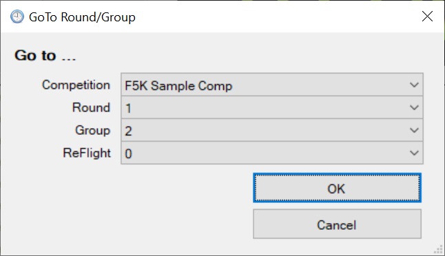
You can 'Go-To' to any Round/Group/ReFlight in the playlist.
- Right-click on the playlist to see the Go-To screen.
- The default values will be for the next flight group.
- Click OK to go to the selected point.
The Round, Group, ReFlight information always shows where you are in the playlist.
When the playlist is running you can -
- Pause, then Resume
- Pause, then Cancel
- Cancel
It is possible to display the Time Of Day.
It is possible to load a newly generated playlist without closing the Digital Timer.
You get this screen by clicking the small arrows at bottom right.
These move the DigitalTimer to a corner of your screen.
This makes it easy to see how the time is going while still making full use of GliderScore.
Click on the small arrows again to restore the screen to full size.
The colour of the computer clock digits will change -
- Orange for preparation time
- Green for working time
- Blue for the landing time (mainly for F3K)
Digital Timer - Display Panels
There are three options for obtaining a suitable external display panel.
- Purchase a commercially made panel such as the one from AerobTec.
Unfortunately AerobTec no longer offer this display panel but
you may be able to buy a pre-owned panel.
- Purchase a display interface board designed and built for GliderScore from
Embedded-Ability.
- Build your own display panel from components.
Each option has obvious advantages and disadvantages.
- The commercially made panel is quick and easy, but may be expensive.
- The display interface board solves all the electronics and programming issues for you,
but requires that you purchase some components and carry out some assembly yourself.
However, comprehensive instructions are provided and nothing more than basic soldering is required.
- Building your own display from components requires good electronics knowledge, programming skills
and construction skills to put it all togther, including the electronics components.
It is possible to make the serial connection using a radio link instead of a cable.
Suitable products can be seen
here
and similar products should be available from other suppliers.
I assume that you would need some electronics knowledge to use this kind of product.
With AerobTec you will have a display panel that looks like this.
A complete solution with no more to do other than make the serial cable connection.
Unfortunately AerobTec no longer offer this display panel. You will have to buy a used one.
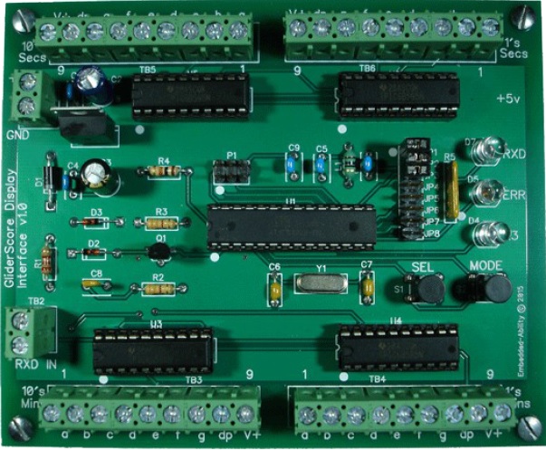
The
Embedded-Ability
display interface board looks like this (actual size 120 x 98.5mm).
Add cabling, 7 segment LED panels, some assembly time and a serial cable connection and it's done.
All cables connect to the board with screw-type terminal blocks, options are activated with
plug-in jumpers, and the user guide provides lots of board and LED display installation help.
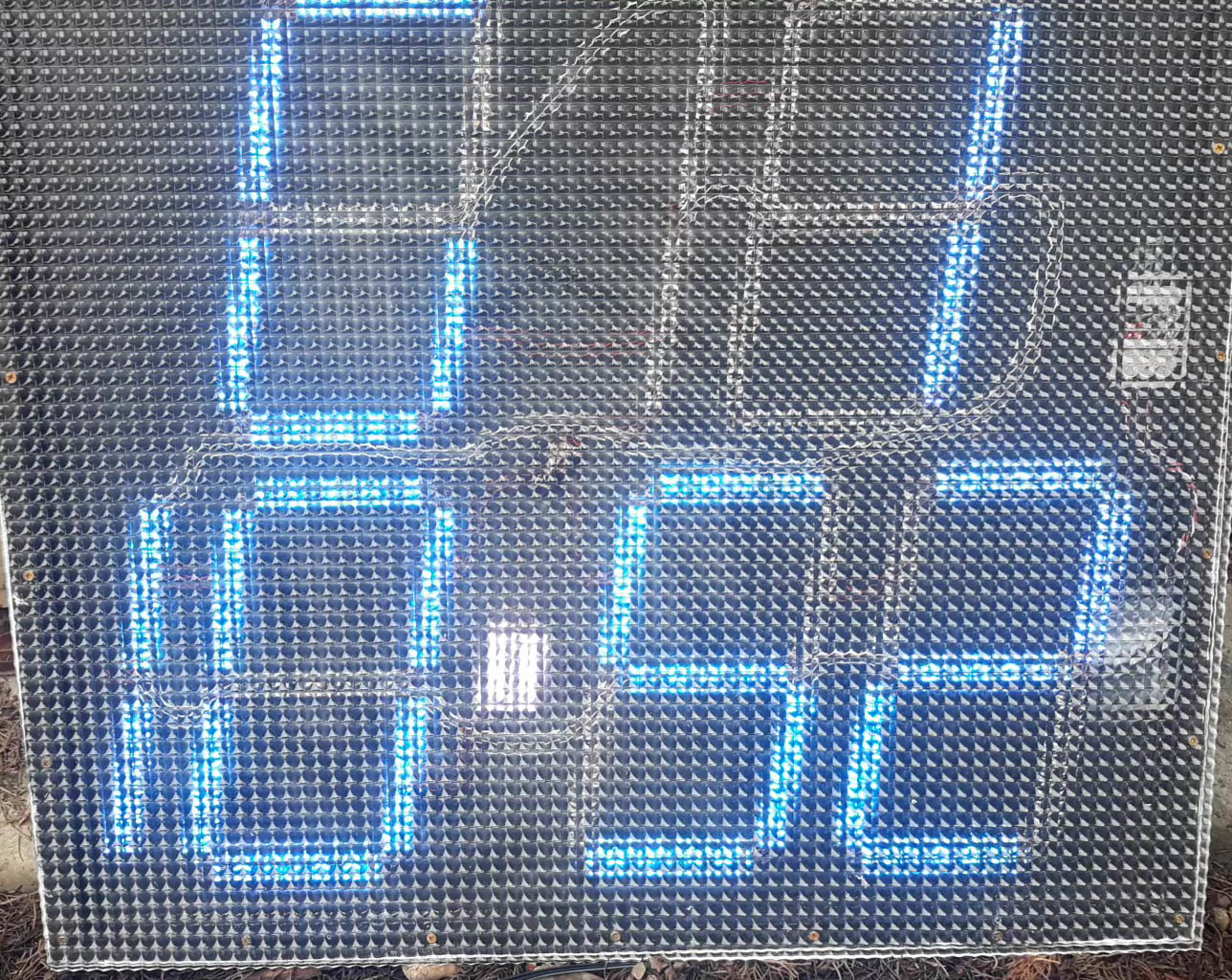
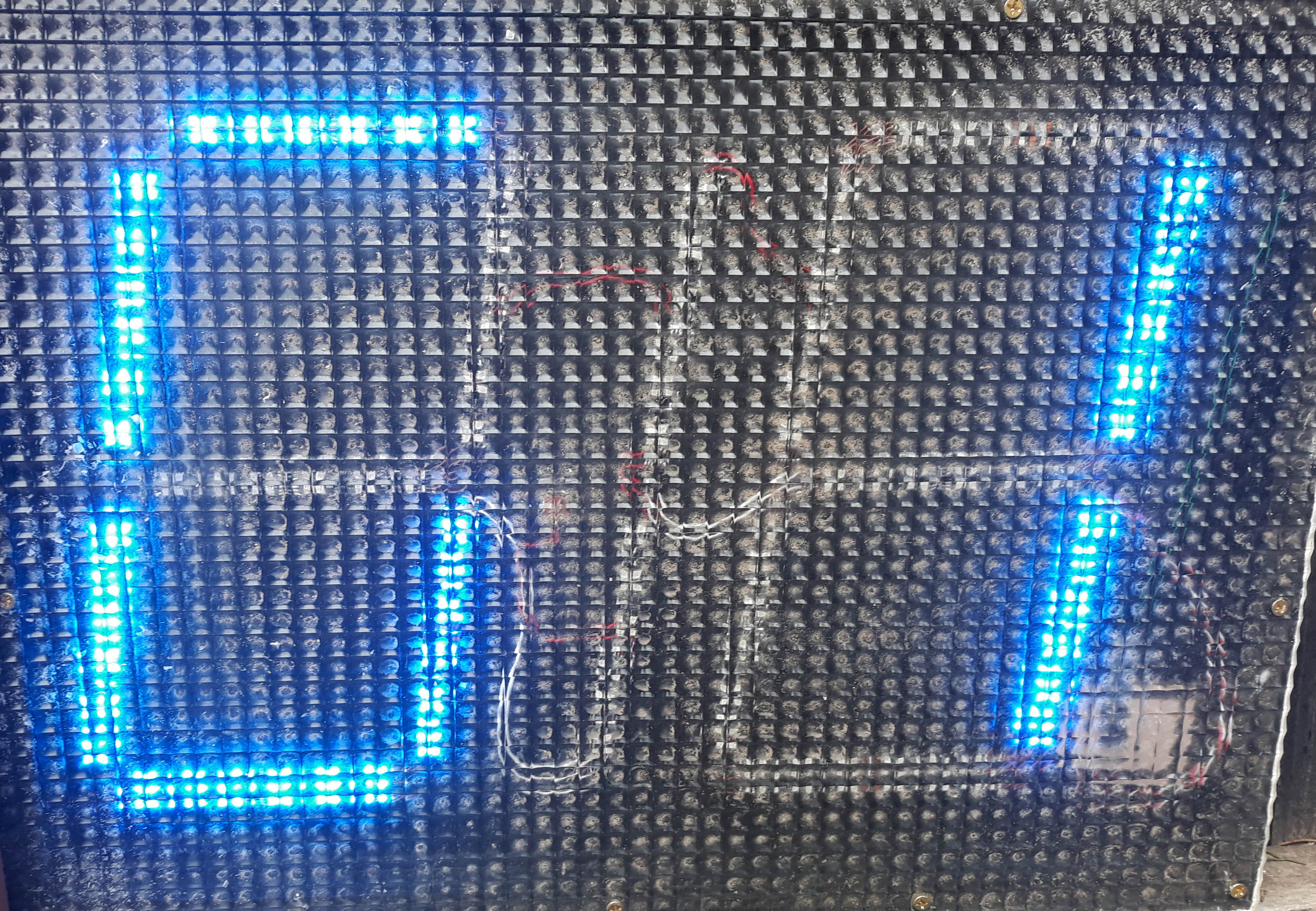
This idea, and images, come from Maarten Broess. Thank you Maarten.
The idea is to cheaply build a display panel using LED strip lighting as shown in the images above.
You will still need a controller such as the one from Embedded-Ability, but you benefit by not having
to either build or buy the LED panels.
I have not seen it all working and I do not know whether the LED strip lighting is bright enough,
but it is worth a try. I believe that wiring it all up would be similar to the wiring described
in the tab 'Display Panel Build'.
If you are after a low cost display board and are prepared to build it all yourself, Robert Budniak has the project for you.
Robert writes ...
"There was previous discussion about LED timing boards. People found these helpful but they all were pretty expensive.
I got thinking and ended designing and constructing some boards.
What I call the Gliderscore Timing Board is used to display the countdown timer, the group and the round information.
What I call the Gliderscore Information Board only displays the Group and Round information
(its purpose is to go near the pits and just keep people informed about the state of the schedule).
A third piece is a small transmitter which connects to the USB port and sends the serial Gliderscore output to the boards,
so no wiring between computer and boards is required.
It's all built around an Arduino running a sketch and serial addressable LEDs. The characters are 250mm (10 inches) in height.
The construction articles are at
Instructables and you'll find the three construction articles, some videos and pictures.
Double-click on the images in Instructables to see the full construction articles.
I hope this adds to the community."
There are some videos on YouTube.
https://www.youtube.com/watch?v=boUfkCiYvWI
https://www.youtube.com/watch?v=Tsda61DY5tw
https://www.youtube.com/watch?v=IN5FRD4WxyA
Digital Timer - Display Panel Build

For this project I decided to build a double sided display panel.
Putting the display panel in the middle of the flight line means that it will easily be seen from both ends.
By setting up the panels at around 30 degrees to each other, they will also be clearly visible from all parts of the landing area.
I have enjoyed carrying out this project and seeing the display panel that I built work for the very first time. A great feeling.
Nothing is really difficult. It all just needs to be thought through before you begin so that there aren’t any surprises.
The Display Panel Build story
Get the printable version of this build project (9 pages .pdf). Click to open
It describes everything, step by step.
Hopefully this document will help you with your own project.
If you need the Silicon Labs USB to TTL drivers, click button to download.
Display Panel Stand
 Pierre Louis LE MESLE of Aéro-Model-Club de Châteaudun France inspired this build by sending me a photo of his display, with stand.
This stand is made of 7m of 32mm diameter pressure PVC pipe with associated fittings.
The pressure pipe fittings are all 90 degrees. I found that drainage pipe and fittings were not suitable.
Pierre Louis LE MESLE of Aéro-Model-Club de Châteaudun France inspired this build by sending me a photo of his display, with stand.
This stand is made of 7m of 32mm diameter pressure PVC pipe with associated fittings.
The pressure pipe fittings are all 90 degrees. I found that drainage pipe and fittings were not suitable.
The ropes are needed because the stand, although strong, is not very stable in the wind.
The ropes are attached using large cable ties and so is the chain that the display hangs from.
There are two short attachments at the bottom of the display to prevent it swinging in the wind.
Approximate dimensions are 1200mm wide x 1700mm high x 600mm deep (width of the base).
I split the uprights to keep the overall length down.
The stand breaks down into 8 pieces
- 1 x top rail
- 1 x bottom rail
- 2 x uprights lower section
- 2 x uprights upper section
- 2 x base pieces
The bottom rail and the two longer (lower) uprights are all the same length so that they are interchangeable.
The two shorter (upper) uprights have a collar at one end.
Below is the detail of the base.
Two T-connectors are used in the centre.

Success!
Have a look at this short video to see how it all worked out in the end.
Note that the time in the video 'jumps' ahead about every 5 seconds so that you don't have to sit through
the full timing sequence of around 12 minutes for one round.
Digital Timer - About
I had a lot of help in developing the Digital Timer and would like to acknowledge the following
- IronRazerz for replying to my question about timers on the MSDN forums.
- Arjan Harmans for testing the program with an actual display panel, creating videos and for many useful suggestions.
- Gerben van Berkum for suggestions and for helping to unravel the syntax of the string to be sent to the serial port.
- Gernot Fink for clarifying exactly what the syntax had to be.
- Denis Truffo (author of F3JTimer) for his support and assistance.
- Lukas Palkovic of AerobTec (former manufacturer of the test display panel) for help at various times.